Difference between revisions of "RFM12 FSK"
| Line 11: | Line 11: | ||
|CODE=[https://github.com/ethersex/ethersex/tree/master/hardware/radio/rfm12 https://github.com/ethersex/ethersex/tree/master/hardware/radio/rfm12] | |CODE=[https://github.com/ethersex/ethersex/tree/master/hardware/radio/rfm12 https://github.com/ethersex/ethersex/tree/master/hardware/radio/rfm12] | ||
}} | }} | ||
| + | |||
| + | The default operating mode of the RFM12 is FSK. This mode is used to treat several Ethersex systems connect by radio | ||
| + | with each other. Here, one of the systems can act as a router to connect to a wired network. | ||
== Connection == | == Connection == | ||
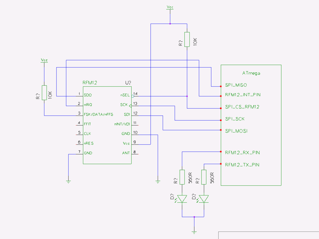
| − | [[Image:Rfm12 connection.png]] | + | If you are using hardware SPI, which is the default, connect the RFM12 to the AVR as follows: |
| + | |||
| + | [[Image:Rfm12 connection.png|640px]] | ||
| + | |||
| + | The SPI connection is pretty fixed and does not need special pinnings. For the chip select (CS) of | ||
| + | the modul and the optional LEDs the pinning must be defined. | ||
| + | |||
| + | /* port the rfm12 module CS is attached to */ | ||
| + | pin(SPI_CS_RFM12, PB0, OUTPUT) | ||
| + | |||
| + | /* port the LEDS for rfm12 txrx attached to */ | ||
| + | pin(STATUSLED_RFM12_TX, PB3, OUTPUT) | ||
| + | pin(STATUSLED_RFM12_RX, PB1, OUTPUT) | ||
| + | |||
| + | RFM12_USE_INT(2) | ||
| + | |||
| + | The RFM12_USE_INT defines whether nRQ is connected to INT0, INT1 or INT2 of the ATmega. | ||
[[Category:RFM12]] | [[Category:RFM12]] | ||
Revision as of 10:20, 6 March 2013
| RFM12 FSK | |
|---|---|
| Status | Stable
|
| menuconfig | Network->IP over RFM12 (FSK transmitter) support |
| Pinning | yes |
| Ecmd | no |
| Control6 | no |
| Requires | UIP_SUPPORT |
| Code | https://github.com/ethersex/ethersex/tree/master/hardware/radio/rfm12 |
The default operating mode of the RFM12 is FSK. This mode is used to treat several Ethersex systems connect by radio with each other. Here, one of the systems can act as a router to connect to a wired network.
Connection
If you are using hardware SPI, which is the default, connect the RFM12 to the AVR as follows:
The SPI connection is pretty fixed and does not need special pinnings. For the chip select (CS) of the modul and the optional LEDs the pinning must be defined.
 /* port the rfm12 module CS is attached to */
 pin(SPI_CS_RFM12, PB0, OUTPUT)
 /* port the LEDS for rfm12 txrx attached to */
 pin(STATUSLED_RFM12_TX, PB3, OUTPUT)
 pin(STATUSLED_RFM12_RX, PB1, OUTPUT)
RFM12_USE_INT(2)
The RFM12_USE_INT defines whether nRQ is connected to INT0, INT1 or INT2 of the ATmega.
