Difference between revisions of "Quick Start Guide/Flashing"
(→Writing the Bytes) |
(→AVR Fuses) |
||
| (4 intermediate revisions by 2 users not shown) | |||
| Line 52: | Line 52: | ||
=== AVRDUDE Configuration === | === AVRDUDE Configuration === | ||
| − | If - and only if - the avrdude executable could be found in your ''PATH'', menuconfig's mainmenu will show an option to enter AVRDUDE configuration | + | If - and only if - the avrdude executable could be found in your ''PATH'', menuconfig's mainmenu will show an option to enter AVRDUDE configuration. |
| − | [[File:avrdude_mainmenu.png]] | + | [[File:avrdude_mainmenu.png|right|sub|thumb|200px|menuconfig's mainmenu with AVRDUDE Configuration selected]] |
| − | + | The AVRDUDE configuration page allows to setup the most common options for avrdude: | |
| − | + | [[File:avrdude_menu.png|right|sub|thumb|200px|AVRDUDE configuration page]] | |
;Programmer Type | ;Programmer Type | ||
| Line 102: | Line 102: | ||
The fuse registers enable/disable or control the basic functionality of the different units of the MCU. One can e. g. enable or disable the Watchdog, the JTAG interface or even the ISP Interface. Configuration of the MCUs clock source or the brown-out detector is also done via the fuse registers. | The fuse registers enable/disable or control the basic functionality of the different units of the MCU. One can e. g. enable or disable the Watchdog, the JTAG interface or even the ISP Interface. Configuration of the MCUs clock source or the brown-out detector is also done via the fuse registers. | ||
| − | |||
| − | '''There is nothing like ''the universal correct fuse setting'' or ''default fuse setting''. Fuse registers are MCU-specific and their correct settings heavily depend on the circuit and parts in use. Be careful, read the datasheet for the MCU acually in use and think twice what is correct for YOUR hardware!!''' | + | '''[[WARNING:]] Programming wrong fuse values may render your MCU UNUSABLE''' (...unless you've access to a JTAG- and/or HV-Programmer.) |
| + | |||
| + | * '''There is nothing like ''the universal correct fuse setting'' or ''default fuse setting''.''' | ||
| + | * '''Fuse registers are MCU-specific and their correct settings heavily depend on the circuit and parts in use.''' | ||
| + | * '''Be careful, read the datasheet for the MCU acually in use and think twice what is correct for YOUR hardware!!''' | ||
| + | * '''Do NOT use generic settings you've found somewhere in the net...''' | ||
| + | |||
;Fuse Low Byte (FLB) | ;Fuse Low Byte (FLB) | ||
| Line 129: | Line 134: | ||
* Reconnect the power, your target should boot up with [[Ethersex]] | * Reconnect the power, your target should boot up with [[Ethersex]] | ||
| − | [[Quick_Start_Guide/Configuration | previous step]] | + | [[Quick_Start_Guide/Configuration | previous step]] |
[[Category:Ethersex]] | [[Category:Ethersex]] | ||
| − | [[Category: | + | [[Category:Quick Start Guide]] |
[[Category:StepByStep]] | [[Category:StepByStep]] | ||
Latest revision as of 19:20, 29 August 2014
Contents
Flashing
After compiling the ethersex.hex you can flash it with avrdude. You can either use avrdude on the command line or call the target program from the Ethersex Makefile.
Prerequisites
- the previously selected board, e.g. AVR NET-IO, ready built and (hopefully) tested
- an ISP-Programmer of your choice supported by avrdude
- an ISP connector cable that fits to your programmer and your board (either 6 or 10-pin)
- an ethersex.hex compiled in the previous step
If you have an ISP-Programmer with a 6-pin port and a board with a 10-pin header - like the AVR NET-IO - you can create an adapter. You can see the pin configuration in figure 4-1 at page 5 AVR042: AVR Hardware Design Considerations. Note that Pin 4 of the 10-pin connector is not used on the AVR NET-IO. GND has to be connected to one of the other Pins (6, 8 or 10).
Flashing the image with avrdude
The following commands are just examples, the actual command line depends on your ISP-Programmer and hardware.
This example is for a serial connection (e.g. the ATMEL Evaluation-Board):
avrdude -v -p m32 -c ponyser -P /dev/ttyS0 -U flash:w:ethersex.hex
This example for a real USB ISP-Programmer:
avrdude -p m1284p -c avrispmkII -P usb -U flash:w:ethersex.hex
For a serial programmer connected via an USB-serial-adapter this may be used:
avrdude -v -p m32 -c stk500v2 -P /dev/ttyACM0 -U flash:w:ethersex.hex
And this one for a parallel ISP-Cable:
avrdude -p m32 -e -c stk200 -U flash:w:ethersex.hex
After flashing remove the ISP-Cable and interrupt the power connection for a short time to reboot the board.
 * -p m32: ATMega32; -p m644: ATMega644; -p ? to list the valid parts
 * -v: display debug messages
 * -c ponyser: traditional serial programmer; -c stkk500v2 for the Atmel board
 * -P /dev/tty.serial the serial port your programmer is connected to; -P COM1 for windows machines; -P usb for USB
 * -U the command you want to execute. In our case we want to flash: -U flash:w:ethersex.hex
Using avrdude from the makefile
Since 16c2a388ec the Ethersex makefile supports two new targets, program and fuses, to invoke avrdude. The target program calls avrdude with the options to flash the previously compiled ethersex.hex to the MCU. The fuses target may be used to program the MCUs fuse registers.
AVRDUDE options and MCU fuse register settings may be configured via a menuconfig dialog. All settings will be saved to the current profile .config.
Available settings and choices on the AVRDUDE configuration page depend on the MCU and clock frequency configured on the General Setup dialog. Please go back to the previous step if you haven't done that yet.
AVRDUDE Configuration
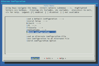
If - and only if - the avrdude executable could be found in your PATH, menuconfig's mainmenu will show an option to enter AVRDUDE configuration.
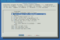
The AVRDUDE configuration page allows to setup the most common options for avrdude:
- Programmer Type
- avrdude option '-c'.
- Use the programmer configuration choosen from the list.
- Refer to the official avrdude documentation if you're in doubt about the correct choice for your programmer (avrdude home).
- NB: The list of choices is generated by calling 'avrdude -c ?' and contains all the programmers your avrdude executable supports.
- Port
- avrdude option '-P'.
- Specify the port the programmer is connected to. Serial devices like ponyprog use for example /dev/ttyS0 (= COM1 under Windows!), most modern programmers use usb.
- Note that most old-style serial programmers will not work properly when connected to an USB-serial-Adapter!
- Extra verbose output
- avrdude option '-v -v'.
- Be more verbose. Default is '-v'. Use this, if you experience problems while flashing or simply want to see in detail whats going on...
- Do NOT verify after programming
- avrdude option '-V'.
- Do NOT verify flash memory after programming. Use with care and only if you're really sure that your setup is perfect. Speeds things up a bit but it's use is generally discouraged.
- Count # of erase cycles in EEPROM
- avrdude option '-y'.
- Tell avrdude to maintain an erase cycle counter in the last four bytes of the eeprom. The counter has to be initialized by calling avrdude with the option '-Y 1' once.
- Do not use this option if your e6 configuration uses the last four bytes of the eeprom.
- Bitclock for ISP or JTAG
- avrdude option '-B'.
- Specify the bit clock period for the JTAG interface or the ISP clock.
- Setting a lower value means higher programming speed. Use higher values if you experience programming errors in your setup.
- The available choices depend on the MCU frequency setting and should not exceed 4/F_CPU in micro seconds:
-
- 4 micro seconds is required for F_CPU < 4 MHz.
- 1 micro second is appropriate for F_CPU < 10 MHz.
- 0.5 micro seconds is appropriate for F_CPU < 16 MHz.
- 0.3 micro seconds is appropriate for F_CPU >= 16 MHz.
- Pass extra options to avrdude
- If your programmer or setup requires any extra options to avrdude you may pass them here.
AVR Fuses
The fuse registers enable/disable or control the basic functionality of the different units of the MCU. One can e. g. enable or disable the Watchdog, the JTAG interface or even the ISP Interface. Configuration of the MCUs clock source or the brown-out detector is also done via the fuse registers.
WARNING: Programming wrong fuse values may render your MCU UNUSABLE (...unless you've access to a JTAG- and/or HV-Programmer.)
- There is nothing like the universal correct fuse setting or default fuse setting.
- Fuse registers are MCU-specific and their correct settings heavily depend on the circuit and parts in use.
- Be careful, read the datasheet for the MCU acually in use and think twice what is correct for YOUR hardware!!
- Do NOT use generic settings you've found somewhere in the net...
- Fuse Low Byte (FLB)
- AVR Fuse Low Byte, two-digit hex value.
- Fuse High Byte (FHB)
- AVR Fuse High Byte, two-digit hex value.
- Extended Fuse Byte (EFB)
- AVR Extended Fuse Byte, two-digit hex value.
The necessary hex values for the fuse registers might be calculated with e.g. an online AVR fuse calculator.
Article on mikrocontroller.net for reference (German).
Writing the Bytes
- Disconnect the power from the target board
- Connect your ISP cable to the programmer and the target board
- Reconnect the power and connect your programmer to the PC
- Execute the command you assembled earlier or type make program
- Congratulations! If avrdude finished without any error you successfully flashed Ethersex to your target board!
- Disconnect the power and the programmer from the target
- Reconnect the power, your target should boot up with Ethersex

